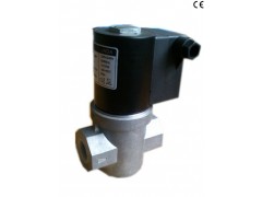
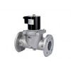
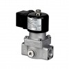
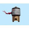
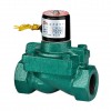
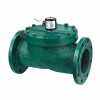
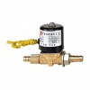
| VS series Solenoid safety valve | |||||||
| Model | Drift diameter(mm) | De |
Connection dimension | Overall dimension(mm) | Flow regulated | Adjustable opening | |
| Length | Hight | ||||||
| VS-15 | 15 | Medium: air and gas. | Rp1/2'' | 91 | 159 | 0.1 | 0.5 |
| VS-20 | 20 | Rp3/4'' | 91 | 159 | 1.9 | 2.3 | |
| VS-25 | 25 | Rp1'' | 91 | 159 | 2 | 2.4 | |
| VS-32 | 32 | Rp11/4'' | 128 | 184 | 5.8 | 6.1 | |
| VS-40 | 40 | Rp11/2'' | 151 | 213 | 5.8 | 6.1 | |
| VS-50 | 50 | Rp2'' | 182 | 286 | 6.4 | 6.7 | |
| (1)The VS type valve is a fast opening solenoid valve that is normally closed.When not energized the spring works on the seat keeping the gas passage closed.When the coil is powered the valve open.When power is cut off the valve rapidly shuts. | |||||||
| (2)This type of device is suitable for gas and air blocking and adjusting controls in atmospheric burners or fan-assisted burners. In industrial ovens and in all gas equipments which use gas solenoid valves(qualified for continuous service-100% ED) | |||||||
| Technical specification | |||||||
| Connection: | Gas threaded ISO 7/1 from Rp3/8''to Rp2''.flangeISO 7005-PN16from DN40 to DN150 | ||||||
| Voltage rating: | 230VAC,110VAC,24VAC/DC,12VAC/DC | ||||||
| Voltage tolerance: | minus 15% or positive 10% | ||||||
| Envirenment temperature: | below 20 degree,or 60 degree | ||||||
| Working pressure: | 200-360 mbar Max | ||||||
| Closing time: | <1second | ||||||
| Protection class: | IP54 | ||||||
| Cable gland: | PG9 | ||||||
| Pressure inlets: | G1/4''on two sides(except brass models) | ||||||
| Limit switch: | by request from 3/4'' to 6'' | ||||||
| Gas type: | Air and non-aggressive gases(EN437) | ||||||
| Filter: | 600um(except brass model) | ||||||
Installation and adjustment
Check correspondence of flow direction with arrow printed on valve body,check correct alignment of connecting pipes and allow enough space from the walls to allow free air circulation.We recommend installing a filter upstream of each installation(open<1mm).Valve may be mounted with coil in horizontal or vertical position.Coil may be oriented 360 degrees in any direction. Install in an area that is protected from rain and water splashes or drops.Capacity may be adjusted from 0 cubic meters/h to the maximum marked on the plate(excepting brass models and 4''-5''-6'' model).Remove coil fastener cap, turn adjustment screw under locking dowel.Make sure that capacity adjustments are made while burners is in operation, and when adjustment is complete screw back locking dowel. Adjustment below 40% capacity are unadvisable since they may cause turbulence
Electrical connection
Remove protection cover and connect power cables to rectifier circuit terminal board. Should cables pass through originally closed opening. use the rubber capsule placed underneath the cap to close any other opening. In case of 12V or 24V powered valves two entries are provided marked with the symbols L/N and +/-(except for flanged models and coils with plastic overinjection) With alternating voltage connect to entries L/N. If it is rectified or direct, with entries+/-.CAUTION:Turn off, all power before servicing any part of the system.
Cleaning and maintenance
Dust and any foreign bodies may be easily removed from the filter or the gas passage zone. After shutting off upstream gas and electric current, remove the coil and unscrew the screws fixing the counter-flange to the valve body. During this operation care should be taken not to cause damage to the seat housing and the teflon sliding clamps.

