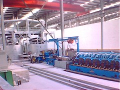
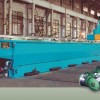
Technical Specifications and Instruction of UL+Z-1500+255/15
Aluminium Continuous Casting & Rolling Line
1. Application
This production line is used to produce conductive aluminum rod of Φ 9.5mm,
Φ12mm by means of continuous casting and rolling.
2. Precise Process Flow
2.1.The process flow chart is as follows:
|
Ordinary aluminum ingot and scrap
|
↓
|
Melting furnace
|
↓
|
Holding furnace
|
↓
|
Continuous casting machine
|
↓
|
Oil Hydraulic shearer
|
↓
|
Continuous rolling machine
|
↓
|
Double basket rod rewinder
|
↓
|
Aluminum rod
|
2.2.Molten aluminum or prepared aluminum melt flows from the holding furnace into the casting machine via the launder, where it is cast into a trapezoid ingot with a cross-sectional area of 2400mm2. The oil hydraulic shearer cuts off the waste end and press it smaller or pointed so as to feed into the rolling machine, where it is rolled, and after passing through the grease box and the guide pipe, aluminum rod is finally laid down in coil in the basket on the trolley.
3. Main Technical Data
Diameter of conductive aluminum rod ∮12mm, and ∮9.5mm
Output capacity: 2.5~5ton/hr.
Overall dimension: 32.05×7.2×4.2m
Total weight: 65t
4. Technical Data of Components
4.1two-wheel continuous casting machine
4.1.1.Diameter of crystallizing wheel: ∮1500mm
4.1.2.Cross sectional area of crystallizing wheel: 2420mm2
4.1.3.Cross sectional area of cast ingot: 2400mm2
4.1.4 Cross shape of crystallizing wheel: M
4.1.5 Casting speed: 8~12m/min (motor speed at 500~1000rpm)
4.1.6.Crystallizing wheel speed: 2~2.546rpm.
4.1.7.Motor power: 4kw (AC, N=1500rpm)
4.1.8.Pressure of cooling water: 0.35~0.5Mpa
4.1.9.Flow of cooling water: 100t/h, in which 60t/h for inner cooling, 40t/h for outer cooling
4.2.Single-track Oil Hydraulic Shearer
4.2.1.Max. shearing force: 12,000kg
4.2.2.Max. shearing stroke: 65mm
4.2.3.Type of electric hoist: TV-0.50
Lifting weight: 500kg
4.2.4.Type of gear pump: YB-25
Oil pressure: 65kg/cm2
Oil output: 25L/min
4.2.5.Type of motor: 4kw, N=960r/min
4.3 Type Y Continuous Rolling Machine
4.3.1.Type: Three rollers in Y-shaped arrangement
4.3.2.Outlet diameter: ∮9.5mm, ∮12mm
4.3.3.Number of stands: 15th 13th
4.3.4.Nominal size of roller: ∮255mm
4.3.5.Transmission ratio between two neighboring stands: 1:1.25
4.3.6.Final rolling speed: V=6.2m/sec.
4.3.7.Center height of rolling: 902.5mm
4.3.8.Main motor power: 250kw, DC, n=500rpm
4.4 Coiler
4.4.1. Coiling motor: Z2-22
Motor power: 1.1kw, DC,
Motor speed: 1500rpm
4.4.2 Speed of coiling head: 15-90rpm
4.4.3 Motor type of gear reducer: JTC561A
Motor power 2.2kw(AC)
Motor speed 48rpm
4.4.4 Size of coil(mm): Φ1800×Φ800×1400(outer dia.×inner dia.×height)
4.4.5 Coil weight : 2t
5. Components and Construction
5.1 5-WheelContinuous Casting Machine
In 5-wheel structure ,it is made of crysttallizing wheel ,compressing wheel ,tensional
Wheel ,guide wheel ,casting system ,cooling system,steel tape blower ,oil filler ,ingot
trimmer and guide bridge.
Drives come from a Y132M2-6 motor, through 3-stage worm gearbox to rotate the crystaillizing wheel, which is fixed on the shaft of min.speed stage and fastened by the cast iron turret to balance the force. Through friction, drives are delivered to rotate crystaillizing wheel,steel tape ,every guide wheel and tensional wheel .The steel tape is compresed and tensioned by pneumatic force so as to be kept in tensional state all the time.
The cooling system of crystallizing wheel consists of inner cooling, outer cooling and side cooling, all of which are installed on a holder in type of openable door. Every cooling are divided into 2 sections for separate inlet, each with a preessure display and a separate adjustable valve. For inner cooling, an additional cooling section is increased to adjust the temperature of crystallizing wheel. The side cooling is installed on the side of baseplate.
The tensional wheel, being installed on the foundation at the lower left of crystallizing wheel, is divided into lower part and upper part, which is fixed on a rotary arm, thrust by a pneumatic cylinder to compress or release.
The compressing device is installed completely on the gearbox of crystallizing wheel while the pressing disk is fixed on a rotary arm, which is thrust by a pneumatic cylinder to compress or release with an adjustable tensional force.
The force of compressing or tension can both be adjusted with the speed regulated by a throttle of air release and noise removal, to prevent the steel tae and crystallizing wheel from impulsion. In the pneumatic system, there is a non-return valve in front of the electrical control switch in order to guarantee the compressing.The working presure of tensional cylinder will not be influenced if the source pressure is somewhat low.
The casting system is equipped with motor for pouring ladle up/down and forward/backward motor, which is convenient to withdraw and put up the pouring nozzle from the trough of crystallizing wheel.
5.2.Single-track Oil Hydraulic Shearer
Used to cut aluminum ingot in irregular shape, it is composed of single-rail hoist, oil hydraulic shearer and oil circuit. The hoist is actually an electric pulley with a lifting capacity of 500kg, traveling along a 6-meter (max. >9m) long rail so as to perform cutting between the casting machine and the rolling Machine. The maximum cross sectional area of the aluminum blank is not larger than 2500 m2 at temperature from 450~550℃, maximum shearing force is 12,000kg, and traveling stroke is 65mm, which is used to cut off the disqualified ingot.
5.3.Rolling Machine
It is composed of 15 stands with rollers of nominal diameter at ∮255mm in Y-shaped arrangement, with upper drive in 7 stands in even number and lower drive in 8 stands in odd number. The rolling pass schedule is in triangle-circular circular-curved arrangement. A main drive mechanism transmits drive from a 250kw through a toothed coupling mated with an axle beneath the 12th stand on the main gearbox. Transmission ratio between two adjacent stands is 1:1.25. Safety toothed couplings are provided between the drive box and the stands, when overloaded, a safety pin is cut off to prevent accident from taking place.
5.4 .Coiler
It is composed of guide pipe, rod rewinder and trolley.
The aluminium rod goes from the rolling stand to the guide pipe at a speed of 6m/s, passing through the grease box, which applies a little lubrication grease on the surface to reduce the friction between the rod and pipe. Then the rod, at a temperature of about 300℃, is easy to go through the coiling head.
The DC motor of coiling head is driven by a gear reducer. By adopting a thyrister speed regulator, it is easy to control the speed so that big coil is made at slow speed while small coil at fast speed inside the basket of take-up trolley.
Two baskets of the same size are on the trolley, beneath which there is an gear reduce motor driven by V-belt to move it when one basket is full so that another basket can move in at the touch of the inch button.
6. Electrical Control System
3-phase, 4-wire, 380V, 50Hz, low-voltage network for power supply, total power 350kw, main motor adopting Siemens full-numeric DC speed regulator, providing with the control cabinet and console for the whole production line, PLC control and touchable screen for operation, all kinds of working data being centralized for monitor and display.
7. Supply scope
7.1 Five-wheel casting machine including 1 set
7.1.1 Crystallizing wheel (with transmission system and inner cooling system)
7.1.2 Compressing device
7.1.3 Tensioner
7.1.4 Outer cooling system
7.1.5 Ingot trimmer
7.1.6 Guide bridge
7.1.7 Casting system (casting ladle only provided with the shell, the refractory
lining to be prepared by customer himself)
7.1.8 Oil coating for steel tape
7.1.9 Main motor
7.1.10 Steel tape 4 pcs. (3 dfor stand-by)
7.1.11 Coolant pump (100 m3/h, 22kW )
7.1.12 Water discharge/charge pump (50 m3/h, 11kW )
7.2 Single-rail oil hydraulic shear 1 set
7.2.1 Oil hydraulic shear
7.2.2 Single-rail hoist
7.2.3 Transmission system
7.3 15-stand continuous rolling mill 1 set
7.3.1 Main gearbox
7.3.2 3-roller Y-type rolling stand 15 stands
7.3.3 Lubrication oil system (with filtering system)
7.3.4 Emulsion system (with filtering system)
7.3.5 Main motor for rolling (with tachmotor)
7.4 TS-1800 pay-off coiler 1 set
7.4.1 Guide pipe and pallet
7.4.2 Rod coiler
7.4.3 Two-direction movable take-up trolley
7.5 Electrical control system 1 set
7.5.1 Operation desk for casting machine
7.5.2 Operation desk for rilling mill(touchable screen)
7.5.3 Operation desk for take-up
7.5.4 Main transmission control cabinet
7.5.5 Emulsion and oil pipe control cabinet
8. List of Consumables
|
No.
|
Drawing No.
|
Description
|
Qty.
|
Material
|
Remark
|
|
1
|
BB05-1-020-025
|
Crystallizing wheel
|
1
|
T2
|
|
|
2
|
BB05-1-120-04
|
Trimming head
|
1
|
Bakelite
|
|
|
3
|
BB05-3-020-014
|
Roller
|
18
|
5CrMnMo
|
|
|
4
|
BB05-3-030-020
|
Roller
|
18
|
5CrMnMo
|
|
|
5
|
BB05-3-060-007
|
Wire delivery pipe
|
14
|
Bakelite
|
4.6.8.10.12.14 Stands
|
|
6
|
BB05-3-040-008
|
Shearing pin
|
14
|
45
|
4.6.8.10.12.14 Stands
|
|
7
|
BB05-3-050-006
|
Upper sliding wheel
|
6
|
45
|
|
|
8
|
BB05-3-050-007
|
Lower sliding wheel
|
6
|
45
|
|
|
9
|
BB05-3-120-023
|
Horizontal roller
|
2
|
5CrMnMo
|
|
|
10
|
BB05-3-130-036
|
Vertical roller
|
2
|
5CrMnMo
|
|

